Enquiries

Enquiries

We would be delighted to hear from you and will can to respond to your email enquiries within 24 hours. Thank you for your interest in Marsh Industries.

    Advanced sewage treatment plant

    Vertical pump chambers

    Pump chambers for housing projects and small commercial developments.

    The Marsh range of vertical pump chambers incorporates systems for pumping surface water or domestic sewage to mains, septic/sewage treatment plant effluent to drainage fields/watercourses, and bespoke systems for larger domestic and industrial applications.

    When discharge to mains is required, but to do so by gravity is impractical, a pump chamber system will be needed. Although available as floor-mounted units for indoor applications such as basements, the vast majority are installed outdoors at levels to suit on-site conditions and topography.

    Guidance notes:

    Where foul water drainage from a domestic property is to be pumped to the mains the effluent receiving chamber should be sized to contain 24-hour inflow to allow for disruption in service, the minimum daily discharge being taken as 150 litres per person per day.

    • For other building types the capacity of the receiving chamber should be based on the calculated daily demand of the water intake for the building, or when only a proportion of the foul sewage is to be pumped then the capacity should be based pro-rata
    • If the sewer is to be ‘adopted’ by a local water authority, please contact Marsh Industries as Sewers for Adoption (SFA) specification and additional local authority related criteria may apply
    Vertical pump chambers

    Operating principle

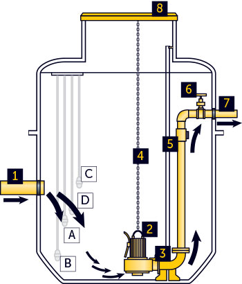
    Each pump chamber contains a number of float switches linked to a control panel that automatically controls flow and levels.

    In a single pump chamber there are three float switches:
    Float A: Actuates the pump cycle until level drops to low level.
    Float B: Low level float stops the pump.
    Float C: High level alarm – positioned above the pump actuator float (min 100mm).

    For twin pump chamber operation there is an additional float switch (Float D) – usually positioned 150mm above first actuator (A) – which actuates the second pump in periods of higher flow.

    After each cycle the pumps alternate to extend pump life and are designed to run for a minimum of 60 seconds with no more than 15 starts per hour.

    KEY

    1. Inlet
    2. Submersible pump
    3. Pump guide rails/pedestal
    4. Pump retrieval chains

    5. Non-return valve

    6. Isolation valve

    7. Outlet

    8. Access cover

    Pump chamber illustration

    Benefits

    • Designed to BSEN12050 for structural strength and water-tightness and to BSEN752 to comply with hydrostatic and electrical requirements
    • Smooth internal walls and integral pump well improves pump efficiency and eliminates ‘dead spots’ which can lead to odours and septicity
    • Pre-assembled pipework for fully automatic operation (pump/control equipment separate)
    • Heavy duty (industrial) ‘peardrop’ floats and Lowara (Xylem) pumps throughout ensure robust, reliable design and maximum efficiency of pump with minimal clogging or wear
    • Unique ‘keying-in’ lip to assist anchoring into concrete surround
    • High level alarm as standard
    • Variable invert depths and orientations ­­­to suit individual site conditions

    Specifications

    Specifications table
    Model Diameter
    +/-50mm
    Height
    +/-50mm
    Inlet invert Inlet dia Outlet invert Outlet dia Storage below invert Total storage
    Mini 600 1100 500 110 300 63 120 234L
    Midi 600 1500 500 110 300 63 280 421L
    Maxi 600 2000 500 110 300 63 421 561L
    CPS1 1170 1100 500 110 300 63 470 867L
    CPS2 1170 1500 700 110 300 63 780 1183L
    CPS3 1170 2200 900 110 300 63 1025 1735L
    CPS4 1170 2600 900 110 300 63 1340 2050L
    CPS5 1958 2100 900 110 300 63 2440 3700L
    CPS6 1958 3400 900 110 300 63 4000 6000L

    All pump chambers are available for dirty water (DW) or sewage (SW), in single pump (SP) and twin pump (TP) configurations.Pump chambers are usually bespoke. The dimensions given on this page are for guidance only.
    For precise tank sizes and configurations, please contact Marsh Industries.
    All dimensions in mm.
    Due to production processes, dimensions of finished units are within a tolerance of +/-2.5%.

    Resources

    Marsh product portfolio and specifications

    PDF